
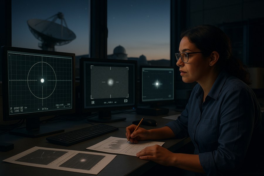
When a case file says “radar contact,” “FLIR video,” or “electro-optical track,” it can feel like the argument is already over: instruments don’t have beliefs, so the reading must be real. But sensor data is not reality itself—it’s a measurement shaped by geometry, calibration, signal processing, and the limits of the hardware. If you want to “find the science, not the fiction,” you have to read sensor claims the way an investigator would: carefully, comparatively, and with an eye for what could generate the same output.
Important note about sourcing (editorial transparency): This is a general, case-file-friendly primer. The version you’re reading does not include inline citations to specific radar/IR/EO engineering references or to any particular UAP case dataset. That means the technical points below should be read as high-level, non-case-specific measurement and analysis considerations, not as claims verified against a released, case-specific “ground truth.” Where system implementations vary, the text is written in “typically/often” language on purpose. Limitation: without sources, this article does not claim to be an authoritative engineering reference—only a structured way to ask better questions of sensor-based UAP claims.
This guide walks you through a practical way to interpret three common sensor streams—radar, infrared (IR), and electro-optical (EO/visible)—and to cross-check them without sliding into either reflexive dismissal or premature certainty. You’ll learn what each sensor type is trying to measure in practice, what common pitfalls can look like, how to ask better questions of the data, and how to separate physical evidence from testimony, inference, disputed claims, and speculation.
Start with a clean evidence stack (before you interpret)
Most case files mix together different kinds of information. Treating them as equal is how weak cases become “mysteries.” A simple evidence stack keeps you honest:
- Physical evidence: recorded sensor outputs (raw or minimally processed), calibrated metadata, authenticated logs.
- Official records: track files, range logs, system health logs, maintenance notes, chain of custody, briefing slides that accurately reflect underlying data.
- Testimony: pilot/operator narratives, observer estimates, after-action recollections.
- Inference: speed/altitude estimates derived from sensor geometry, correlations (“it was the same object”), “must be” conclusions.
- Disputed claims: statements contradicted by other records or lacking supporting documentation.
- Speculation: origin or intent (“non-human,” “black project,” “probe”) without direct evidence.
As you read, keep asking: Which layer is this claim coming from? A case built mainly on inference and recollection can still be interesting, but it isn’t the same as a case built on well-preserved instrument data.
Radar 101: what it measures—and what “a track” really means
Radar is often treated as the strongest pillar because it can provide distance-to-return and (in many configurations) some kind of velocity information. But radar outputs are the end of a long pipeline: emission, reflection/scattering, reception, filtering, tracking logic, and operator display. Exactly how these steps behave depends on the specific radar, its operating mode, the environment, and its signal processing.
What radar can directly measure (at a high level)
- Range: distance to a return, commonly inferred from signal travel time in ranging radars.
- Angle (bearing/elevation): direction to a return, depending on antenna and processing.
- Radial velocity: motion toward/away from the radar can be inferred in Doppler-capable systems and modes (system-dependent).
- Signal strength and quality metrics: often available internally even if not shown on a simple display.
What a radar “track” is (and why it matters)
A “track” is typically a software hypothesis that multiple detections across time belong to the same object. Trackers can smooth and predict motion and may also coast (continue a track briefly through missed detections). This is valuable operationally, but it can mislead analysis if a track display is treated as a perfect record of continuous measurement.
Common radar pitfalls seen in UAP discussions (examples, not a diagnosis)
- Clutter and anomalous propagation: Weather and propagation conditions can change where/when radar sees returns. (The details are system- and environment-dependent.)
- Multipath: Reflections off the sea or terrain can generate ambiguous geometry (“ghosts”) and bias some inferred parameters in some configurations.
- Track swaps/merges: Two nearby objects (or clutter patches) can cause a tracker to jump identity, depending on tracker logic and scenario.
- Chaff and other countermeasures: Some radars may track clouds of reflectors under some modes/settings if not filtered or identified as such.
- Coordinate confusion: Ground speed vs radial speed; barometric vs geometric altitude; local vs absolute frames.
Radar questions that improve almost any case file
- What radar type and mode was used (search vs track, pulse-Doppler vs other), and what filtering was active?
- Do we have detections (plots) with timestamps, or only a narrative and screenshots?
- What were the weather and propagation conditions? Any notes about clutter/ducting/anomalous propagation?
- Was IFF/transponder information present or absent—and how was “unknown” defined in that system/context?
- Is the reported speed/altitude coming from direct measurement, or derived from a displayed track?
IR (thermal/FLIR) 101: brightness is not temperature
IR video is compelling because it feels like you’re seeing heat. But many airborne “FLIR-style” systems map detected IR radiation into an image where brighter/darker pixels are display choices (polarity, gain, level) layered onto a measurement that depends on distance, atmosphere, optics, and target material properties. Some systems can produce radiometric (quantitative) outputs; many publicly shared clips are display products rather than calibrated temperature maps.
What IR sensors are actually detecting (high-level categories)
In simplified terms: IR sensors measure incoming infrared radiation in certain wavelength bands. That radiation can come from:
- Thermal emission (object temperature, modified by emissivity).
- Reflected IR (especially when strong sources and reflective materials/angles are involved).
- Atmospheric effects (absorption and scattering that change with humidity, path length, and wavelength band).
IR pitfalls that can inflate UAP claims
- Gain/level changes: Auto-gain can make a dim object look like it blooms or shrinks; manual changes can do the same.
- Polarity confusion: “White hot” vs “black hot” reverses intuitive interpretation.
- Zoom and point spread function: Distant unresolved sources can appear as blobs whose apparent size/shape changes with focus/zoom and processing.
- Apparent “cold” targets: A target can look cold if it’s reflective and mirroring a cold sky, or if the background is hotter (noting that “cold/hot” here is relative-to-display unless radiometric).
- Gimbal/aircraft motion: “Object motion” can be dominated by sensor slewing and ownship turns unless stabilized metadata (sensor line-of-sight and platform telemetry) is used.
IR questions to ask (practical checklist)
- Is the video radiometric (quantitative) or display-only?
- What are the sensor settings over time (gain, level, zoom, FOV, polarity)? Do we have an overlay?
- What is the line-of-sight geometry: range estimate, slant angle, and background (sea/sky/cloud)?
- Is there evidence of focus change, saturation, or compression artifacts?
- Can we correlate timestamps to radar hits or EO frames?
EO (visible) 101: you’re mostly measuring light, optics, and geometry
EO footage—phone videos, cockpit cameras, shipboard optics—often becomes the most shared “evidence” because it looks familiar. The trap is that familiar-looking imagery can hide unfamiliar optical artifacts.
What EO can do well
- Angular motion: How an object moves across the frame over time.
- Shape cues: Sometimes, if the target is resolved and in focus.
- Context: Stars, horizon, clouds, landmarks that constrain geometry (if stable and not distorted).
What EO usually cannot do by itself
- Range: Without stereo, known size, focus calibration, or usable parallax, distance is often ambiguous.
- Speed: Speed requires distance; without it, you mostly have angular rate.
- Size: Apparent size in pixels depends strongly on focus and saturation (blooming).
EO pitfalls worth learning once (and applying forever)
- Autofocus hunting: Can make point objects appear to expand/contract, sometimes looking like “shape shifting.”
- Rolling shutter and stabilization: Fast pans can skew shapes or create wobble that looks like motion, depending on camera and processing.
- Bokeh and aperture artifacts: Out-of-focus point sources can take on polygonal or “craft-like” shapes tied to the lens/aperture.
- Compression and sharpening: Edge enhancement and compression can create misleading texture, edges, or motion impression—especially on small, distant targets.
- Parallax vs distant motion: Nearby objects (birds, balloons) can show dramatic apparent motion against a distant background.
How to cross-check radar + IR + EO without fooling yourself
The most useful habit is to treat each sensor as a different question about the scene:
- Radar: “Is there a coherent return at these bearings/ranges over time (per this system’s detection logic)?”
- IR: “Is there an in-band source along this line of sight, and how does it change with settings/geometry?”
- EO: “Is there a visible light source/object, and what is its angular behavior relative to the frame?”
Step-by-step convergence test (a practical method)
- Unify the timeline. Get every timestamp into the same reference (including time zone, clock drift notes, and frame rates). If the case file doesn’t provide this, treat correlations as tentative.
- Lock the geometry. Record ownship position, altitude, heading, and sensor pointing angles if available. Many dramatic interpretations can weaken when platform motion is accounted for.
- Match lines of sight. If IR/EO is looking at bearing X while radar contact is at bearing Y, you may be comparing different things—even if it feels like the “same object.”
- Look for independence. If IR cueing came from radar, and the radar track is later “confirmed” by pointing IR at it, you have a linked system. That doesn’t make the observation useless, but it does reduce the strength of “independent confirmation” language.
- Stress-test mundane hypotheses. Ask what would happen if the target were a distant aircraft, a balloon, a bird, a drone, a star/planet, or clutter. Which sensors would see it, and how would it look under the observed settings?
- Only then estimate performance. Compute speed/acceleration only after you have a defendable range estimate and a credible error budget.
Steel-manning both sides: conventional vs unconventional interpretations
Taming Gravity’s standard is not “debunk” or “believe.” It’s: What does the data actually require? Here’s a fair-minded way to frame competing interpretations.
Conventional explanations (strongest version)
- Mis-estimated range: Many extraordinary kinematics rely on assumed distance.
- Sensor artifacts: Tracking software, stabilization, gain changes, multipath, or propagation can create convincing “objects.”
- Ordinary targets in unusual conditions: Balloons, birds, aircraft, satellites, and atmospheric phenomena can look strange when viewed at long range through complex optics and processing.
- Human factors: High workload, expectation effects, and memory reconstruction can shift testimony away from instrument reality.
Unconventional explanations (strongest version)
- Genuinely novel craft or devices: If multiple measurements (ideally across independent platforms) provide consistent range/velocity/geometry and eliminate common artifacts, an unknown vehicle class becomes a live hypothesis.
- Novel atmospheric/plasma phenomena: Some reports may involve poorly characterized natural phenomena that can interact with sensors in non-intuitive ways.
- Electronic warfare / spoofing: In some operational contexts, deliberate deception could generate misleading radar/EO/IR cues—though proving this requires specific technical indicators that are rarely released publicly.
What “missing evidence” usually decides the case
Many public-facing case files contain videos and anecdotes but omit the metadata that would allow rigorous reconstruction. Without naming any specific release as representative, these are high-value missing pieces when you’re trying to do a serious reconstruction:
- Raw or minimally processed sensor data (not just edited clips).
- Calibration and system state (focus, zoom, gain/level, radar modes, fault logs).
- Precise ownship telemetry (position, attitude, speed) synchronized to the imagery.
- Environmental context (weather, sea state, cloud layers, temperature/humidity profiles).
- Independent corroboration (another platform’s sensor with independent cueing, or ground truth like ADS-B/flight plans where appropriate).
How to write (or read) a responsible sensor-based UAP summary
If you’re documenting a case for others—or sanity-checking someone else’s write-up—use a format that keeps evidence and inference separate:
- What is directly measured: “Radar detections at these times/bearings/ranges” / “IR object present in this FOV at these timestamps.”
- What is derived: “Assuming a range of X–Y, the speed would be…”
- What is disputed/unknown: “No range is available from the EO clip alone.”
- What mundane hypotheses were tested: aircraft, balloon, birds, astronomical objects, clutter, propagation, spoofing—explicitly.
- What would change your mind: specify what additional data would confirm or falsify the leading interpretations.
Where this fits in the Taming Gravity approach
Conclusion: a disciplined way to stay curious
Radar, IR, and EO can each contribute real, valuable evidence—but only if you interpret them as measurements with constraints, not as self-interpreting truth machines. The most reliable path is to (1) build a clean evidence stack, (2) understand what each sensor can and cannot measure, (3) cross-check timelines and geometry, and (4) test conventional explanations as aggressively as you test exotic ones. That approach won’t solve every case, but it can help separate “interesting data problems” from “extraordinary claims built on missing context.”
Q&A
If a UAP is “on radar,” does that prove there was a solid object?
Not by itself. Radar indicates a return that the system treated as a detection, and a tracker may turn detections into a smoothed “track.” Solid objects can do that, but so can clutter, multipath reflections, unusual propagation, or countermeasures. Strong cases provide underlying detections, quality metrics, system mode/state, and a clear geometry—not just a track display or narrative.
Does a bright IR/FLIR target mean it’s extremely hot?
Not necessarily. Many IR videos are display products shaped by gain/level and polarity, and brightness depends on distance, atmosphere, emissivity, and sometimes reflected IR. Without calibrated radiometric data and enough context to model the viewing path, IR footage usually supports relative statements (“brighter in-band than background”) more than precise temperature claims.
Why do some UAP videos show “instant acceleration” or “impossible speed”?
Often because speed is inferred from angular motion using an assumed distance. If the target is much closer or farther than assumed, the implied speed changes dramatically. Platform motion, stabilization artifacts, zoom changes, and tracking behavior can also create the appearance of sudden motion. Credible kinematics require a defendable range estimate and synchronized platform telemetry.
What’s the most important metadata missing from many public UAP releases?
Time-synchronized sensor pointing and platform telemetry (position, altitude, attitude), plus sensor settings (zoom, gain/level, focus) and system mode/state. With those, analysts can reconstruct geometry, distinguish object motion from camera motion, and estimate uncertainties. Without them, many correlations and performance claims remain speculative.
What does “multiple sensors confirmed it” actually mean in a strong case?
Ideally it means measurements that agree on timing and geometry, with transparent cueing pathways and uncertainty estimates. “Independence” matters: if one sensor cues another, that’s valuable operationally but weaker as confirmation. The strongest convergence uses separate platforms or sensor types that can corroborate without sharing the same failure modes.














Leave a Reply